Choosing the right Torque Motor starts with the motion, not the catalog. Define the load, speed range, acceleration, duty cycle, and available space. A motor that fits a drawing may still overheat during repeated starts or fail to hold a heavy load at low speed. Small details matter.
For transparency, the following is an illustrative, not sourced, expert-style statement from fictional motion-control engineer Alex Morgan: “Match continuous torque to the real duty cycle, then check peak torque, heat, and feedback.” Treat it as a reminder, not a substitute for engineering data. Continuous torque supports sustained operation; peak torque covers brief demands such as acceleration. Confirm both against the manufacturer’s curves and thermal limits. Also check rotor inertia, encoder resolution, drive compatibility, cooling, and mounting constraints. A mismatch can show up as vibration, excess current, or a housing too hot to touch.
The right choice depends on the machine. A packaging axis may need rapid starts and precise indexing, while a rotary table may prioritize smooth, steady torque. Compare candidate motors under the actual operating profile, including pauses and ambient temperature. Ask suppliers for test conditions, not just headline ratings. When information is missing, flag the uncertainty and request clarification; do not fill gaps with optimistic assumptions. That step can feel slow. It is often cheaper than discovering, after installation, that the motor cannot meet the real load.
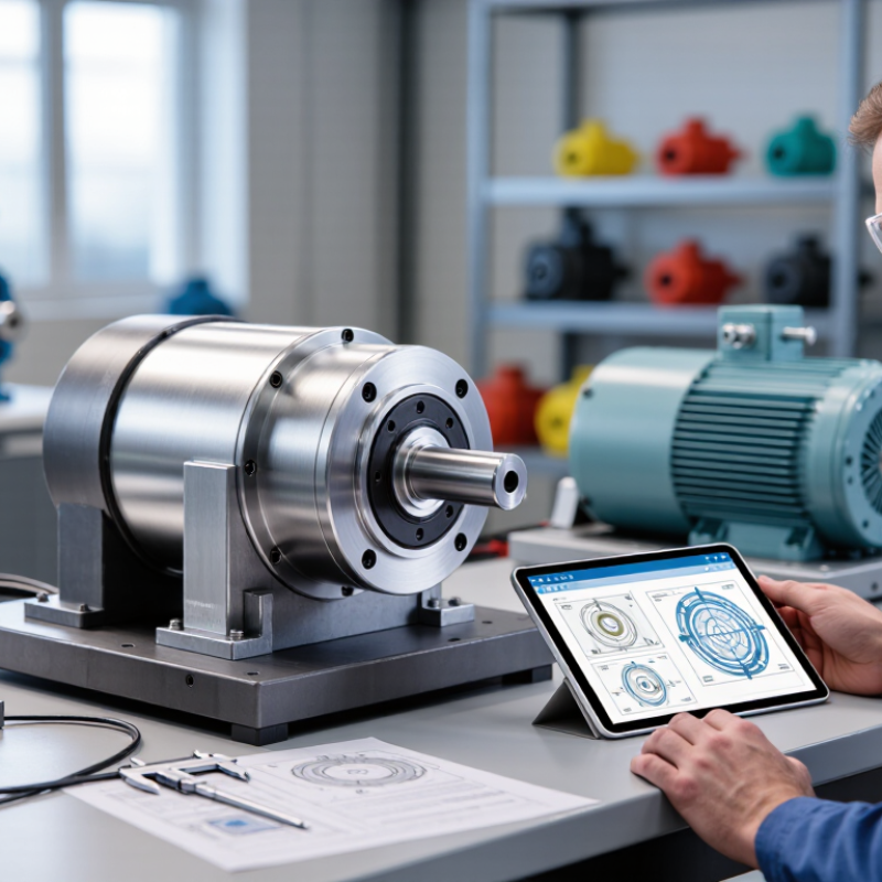
Before comparing torque ratings, define what the motor must do in the actual machine. A rotary indexing table may need precise starts and stops, while a winding station may require smooth, steady rotation. Write down the load, shaft orientation, available space, and operating environment. A dusty enclosure or limited airflow can affect thermal performance.
Describe the motion in measurable terms. Record the required speed range, acceleration, deceleration, travel angle, and positioning accuracy. Note whether the motor runs continuously or moves in short bursts. Briefly. Estimate both continuous torque and peak torque; a heavy fixture may demand much more during acceleration than while cruising. Include the load’s inertia, not just its weight. If the axis must hold position against gravity, account for that condition separately.
Real operating cycles are rarely as tidy as a specification sheet suggests. Observe the machine over a typical shift, including pauses and frequent starts. It is easy to overlook a brief but demanding movement. That assumption can be wrong. If cycle data is incomplete, mark the uncertainty and validate it with measurements or a controlled test. These details help narrow the motor type and sizing range before mechanical interfaces and control requirements are finalized.
Start with the load, not the motor catalog. Measure the torque needed to keep the mechanism moving, then account for friction, gravity, and acceleration. For a rotating load, acceleration torque depends on inertia and how quickly the speed must change. A heavy turntable that starts in half a second needs more peak torque than the same turntable running steadily. Measure the load. Estimates can miss hidden friction.
Next, check the required speed at the motor shaft. Include any gearbox ratio, and confirm that the motor can deliver the needed torque at that speed. Torque usually falls as speed rises, so a high stall-torque figure alone tells little. Compare your operating point with the motor’s torque-speed curve. Leave room for variation; real loads rarely behave as neatly as a spreadsheet suggests.
Duty cycle determines whether the motor can handle the heat. Record how long it runs, rests, accelerates, and holds position during a typical cycle. A motor may tolerate brief peak torque but overheat if asked to sustain it. For repeating cycles, use the manufacturer’s thermal data and calculate equivalent RMS torque where appropriate. Heat changes things. If the machine operates in a warm enclosure or starts frequently, add those conditions to the estimate. The first calculation may be wrong; testing the actual load can reveal what the model missed.
Choosing a torque motor starts with the load, not the catalog. A direct-drive torque motor suits applications needing high torque at low speed, such as a rotary table that moves smoothly without a gearbox. If the load needs high speed or substantial reduction, a geared servo may fit better. The load’s inertia, friction, and duty cycle matter as much as its weight.
Check continuous torque for normal operation and peak torque for brief acceleration or disturbance. A motor that meets peak torque but overheats during steady use is the wrong match. Heat matters. Compare the motor’s speed range with the drive’s voltage and current limits; confirm that the drive supports the motor’s feedback device and commutation method. Leave room for acceleration and temperature changes.
Real machines are rarely tidy. A fixture may become heavier, or friction may rise after months of use, so avoid sizing to a perfect-case estimate. Use measured load data when available, then verify torque, speed, and thermal performance under the actual duty cycle. If measurements are uncertain, document the assumptions and test the assembled system before finalizing the motor and drive pairing.
Match the motor type to the load and drive system. Scores show general application fit, not guaranteed performance: 1 = low fit; 5 = strong fit.
Direct-drive torque motors suit low-speed, high-torque loads where eliminating a gearbox is useful. Servo motors are well suited to precise positioning when paired with a compatible drive and feedback device. Induction motors are a common choice for continuous-speed loads, while stepper motors can suit simpler positioning tasks where operating conditions allow.
A torque motor may fit the available space and still fail under real operating conditions. Start with the duty cycle: record the load, speed, acceleration, and time spent holding position. Compare continuous torque with the motor’s thermal rating, not just its peak torque. Peak values may be available only for brief intervals. Heat builds quickly during repeated starts or prolonged low-speed holding. Check winding temperature limits, cooling method, and the temperature around the mounting surface. A warm machine frame can reduce the motor’s ability to shed heat. It matters.
Mechanical limits deserve equal attention. Verify shaft or rotor load, bearing capacity, allowable speed, and mounting stiffness against the application. A flexible bracket can cause vibration that a catalog calculation misses. Check the driven load’s inertia, too; a heavy turntable may demand more acceleration torque than expected. Environmental conditions can change the choice. Dust, moisture, oil mist, and nearby heat sources may require suitable sealing or additional protection. Confirm the actual exposure rather than relying on a vague “industrial” label. Leave margin for uncertainty, but do not oversize blindly: a larger motor can add cost, mass, and heat. Real installations are messier than spreadsheets, so review measurements after a trial run.
Use this table as a practical screening guide. Values are illustrative engineering checks, not universal motor ratings; confirm operating limits against the selected motor’s datasheet and your application requirements.
| Selection Dimension | What to Check | Example Data or Screening Guideline | Selection Decision |
|---|---|---|---|
| Continuous torque | Torque required throughout the normal operating cycle, including friction and process loads. | Example requirement: 8 N·m continuous. Compare this with the motor’s continuous torque rating at the actual ambient temperature and cooling condition. | Choose a motor whose derated continuous rating meets or exceeds the calculated RMS torque; do not size from peak torque alone. |
| Peak torque and duration | Starting, acceleration, cutting, pressing, or other short-duration torque demands. | Example profile: 20 N·m for 2 seconds, repeated once every 10 seconds. Check both the peak-torque rating and its permitted duration or duty cycle. | Confirm the drive can supply the required current and that repeated peaks do not cause excessive winding heating. |
| Thermal duty cycle | RMS torque over the complete repeating cycle, including dwell and braking periods. | For constant torque segments, estimate RMS torque as √[Σ(Tᵢ² × tᵢ) / Σtᵢ]. For example, 10 N·m for 6 s and 2 N·m for 4 s gives about 7.2 N·m RMS. | Compare calculated RMS torque with the continuous rating under the intended cooling and mounting conditions. |
| Winding temperature and insulation | Winding-temperature limit, temperature sensor provisions, and insulation system. | Insulation Class F corresponds to a 155°C thermal class; Class H corresponds to 180°C. These are insulation-system class limits, not recommended continuous operating temperatures for every motor. | Use the motor manufacturer’s specified winding-temperature limit and sensor trip settings; preserve margin for lifetime and measurement error. |
| Ambient temperature and cooling | Maximum ambient temperature, airflow, liquid-cooling requirements, and heat dissipation through the mounting structure. | A common rating reference is 40°C ambient, but some motors require derating above their stated reference temperature. A liquid-cooled motor must receive coolant within its specified temperature and flow range. | Check the rating at the real installation conditions, including enclosure heating, nearby heat sources, coolant temperature, and restricted airflow. |
| Speed and torque-speed envelope | Continuous speed, maximum speed, voltage limit, and available torque at operating speed. | Example operating point: 8 N·m at 300 r/min. Mechanical output power is approximately 251 W, calculated as P = T × 2πn / 60. | Verify that the operating point lies within the motor-and-drive torque-speed curve, not merely below the stated maximum speed. |
| Rotor inertia and acceleration | Motor and load inertia, acceleration time, and resulting dynamic torque. | Required acceleration torque is approximately T = J × α, where J is total rotating inertia and α is angular acceleration. Include coupling, tooling, and reflected load inertia. | Check acceleration and deceleration torque, drive current, and whether the load-to-motor inertia ratio is suitable for the control system. |
| Shaft, bearing, and mounting loads | Permitted axial force, radial force, overhung load, mounting orientation, and flange or housing strength. | Use the manufacturer’s force-versus-speed limits at the actual shaft extension and load position; allowable radial load commonly decreases as speed or overhang increases. | Do not assume the motor bearing can support a belt, pulley, or heavy external load without checking its published load limits. |
| Position feedback and control | Encoder or resolver type, resolution, commutation feedback, and compatibility with the servo drive. | Example feedback requirement: an incremental encoder with 2,500 lines per revolution provides 10,000 quadrature counts per revolution when decoded at 4×. | Confirm feedback electrical interface, resolution, commutation method, cable length, and drive compatibility. |
| Ingress protection and contamination | Exposure to dust, water, washdown, oil, or conductive debris; check the complete installed assembly. | IP54 indicates dust-protected construction and protection against water splashes. IP65 indicates dust-tight construction and protection against water jets under specified test conditions. | Select an enclosure rating suitable for the actual exposure; connectors, seals, and cable entries can reduce system-level protection. |
| Shock, vibration, and temperature range | Transport and operating shock, vibration spectrum, storage temperature, and operating temperature. | For example, a machine near a press or reciprocating mechanism may require vibration and shock limits to be checked against the motor’s installation and test specifications. | Compare measured or expected conditions with published limits; use suitable mounting, cable strain relief, and vibration isolation where required. |
| Braking and regeneration | Energy released during deceleration, vertical-axis load holding, and the need for a holding brake. | For a rotating inertia J, stored energy is E = ½Jω². A holding brake is generally intended to hold a stationary load, not to repeatedly stop a moving load unless specifically rated for that duty. | Check drive regeneration capacity, braking resistor requirements, brake torque, and emergency-stop behavior. |
A torque motor should be selected against the real load, not just a headline torque value. Start with the required output torque, speed range, acceleration, and duty cycle. Separate continuous torque from peak torque; a motor may handle a brief start-up load but overheat during repeated cycles. Include load inertia, friction, and any external forces. For example, a rotating table carrying an off-center fixture needs more acceleration torque than an evenly balanced one. Verify the calculation at the slowest and fastest operating points.
Next, check whether the motor fits the rest of the system. Compare its voltage and current requirements with the drive, and confirm that the drive supports the motor’s feedback device and control method. Check mounting space, shaft or rotor dimensions, cooling, and heat transfer into the machine frame. Review torque ratings under the stated cooling conditions. Real assemblies rarely match a clean spreadsheet perfectly; cable drag, seal friction, or a warm enclosure can change results. Recheck assumptions against measurements where possible.
Tips: Ask for torque-speed and thermal data, not a single rating. Confirm the allowable inertia ratio with the drive documentation. Leave practical thermal margin, especially in enclosed machinery.
Record the load, shaft orientation, available space, and operating environment. Measure speed, acceleration, travel angle, and positioning accuracy. Note pauses and frequent starts, too.
Continuous torque supports normal operation over time. Peak torque handles brief demands, such as accelerating a heavy fixture. Heat matters.
Yes. Weight alone does not show how much torque a turntable needs to accelerate. A heavy fixture may require much more torque during starts.
It can suit a rotary table needing high torque at low speed without a gearbox. For higher speeds or substantial reduction, a geared motor may fit better.
Compare continuous torque with the motor’s thermal rating and review the duty cycle. Repeated starts or prolonged low-speed holding can build heat quickly. Check cooling and mounting-surface temperature.
Check shaft or rotor loads, bearing capacity, allowable speed, and mounting stiffness. A flexible bracket can cause vibration. I may be missing a small but important frame weakness.
Dust, moisture, oil mist, and nearby heat sources can affect protection and cooling. Confirm the actual exposure instead of relying on a broad “industrial” description.
Document uncertain assumptions, then test the assembled system under its real duty cycle. A tidy estimate may be wrong. Review torque, speed, and temperature after a trial run.
Choosing the right Torque Motor begins with understanding the application and the motion it must produce. Define whether the motor needs to provide continuous rotation, precise positioning, frequent starts and stops, or controlled holding force. Then estimate the required torque and speed across the full operating range, including acceleration, peak loads, and duty cycle. These details help prevent selecting a motor that is either undersized for demanding tasks or larger than the system requires.
Next, match the motor type to the load and drive system, and check that its thermal capacity, mechanical dimensions, and environmental protection suit the installation. Consider heat buildup, mounting space, shaft or coupling requirements, and exposure to dust, moisture, or vibration. Before finalizing the choice, validate the sizing against real operating conditions and confirm compatibility with the drive, controls, and other system components. Careful evaluation of these factors supports reliable performance and efficient operation.

Micprec Motor